Sheet Metal Basics
Sheet metal fabrication is a manufacturing process that transforms flat metal sheets into three-dimensional parts
through cutting, bending, and forming operations. Understanding the fundamental concepts and terminology is essential
for designing effective sheet metal components.
What is Sheet Metal?
Sheet metal refers to metal formed into thin, flat pieces with uniform thickness. Common materials include steel,
aluminum, stainless steel, copper, and brass. The thickness typically ranges from 0.5mm to 6mm, though specifications
vary by application and material type.
Core Components of Sheet Metal Parts
Every sheet metal part consists of distinct features that define its geometry and function. Understanding these
components helps in both design and manufacturing.
Flanges
A flange is any flat, planar section of a sheet metal part. These are the bearing surfaces where the material remains
unbent and flat. Flanges form the primary functional surfaces of most parts and are where holes, cutouts, and other
features are typically located.
Bends
Bends are the curved transitions that connect flanges together. When sheet metal is bent, the material forms a
cylindrical surface with a specific radius. The bend transforms a flat sheet into a three-dimensional structure while
maintaining material thickness throughout the transition.
Hems
A hem is a special type of bend where the edge of the sheet is folded back onto itself. Hems serve multiple purposes
including edge strengthening, safety (eliminating sharp edges), and aesthetic finishing. Common hem types include open
hems, closed hems, and teardrop hems.
Thickness Faces
These are the exposed edges of the sheet metal that reveal its thickness. Thickness faces appear at the perimeter of the
part and at any cutouts or holes. While often overlooked in design, these surfaces are important for assembly
considerations and edge finishing.
Holes and Cutouts
Sheet metal parts frequently include various types of holes and cutouts for assembly, ventilation, weight reduction, or
functionality. Holes are classified based on their relationship to the flange edges. An isolated hole sits completely
within a flange without touching any edges, while a non-isolated hole intersects with the flange boundary. Countersink
holes include angled geometry to accommodate fasteners with tapered heads.
Understanding Bends
The behavior of material during bending is fundamental to sheet metal design and manufacturing.
Bend Angle
The bend angle measures the angular relationship between two adjacent flanges. It ranges from 0 degrees (completely
flat) to 360 degrees (a complete roll). A 90-degree bend is the most common, creating perpendicular flanges. The bend
angle directly affects the final part geometry and the forces required during forming.
Bend Direction
Bend direction indicates whether material folds upward or downward relative to a reference surface, typically the root
flange. This distinction matters for tooling setup, part orientation during manufacturing, and ensuring bends don't
interfere with each other in complex geometries.
Bend Radius
The bend radius is the inside radius of curvature where the material bends. This critical dimension affects both the
manufacturing process and the final part strength. Smaller radii create sharper bends but risk cracking the material,
while larger radii are easier to form but consume more material. The minimum bend radius depends on material type,
thickness, grain direction, and forming method.
Local Bend Radius
In parts with multiple bends, each bend can have its own specific radius. The local bend radius refers to the individual
radius value for a particular bend, allowing for optimized designs where different bends require different
characteristics.
The Unfolding Process
One of the unique aspects of sheet metal is that three-dimensional parts begin as flat patterns. Understanding how bent
parts relate to their flat development is crucial for accurate manufacturing.
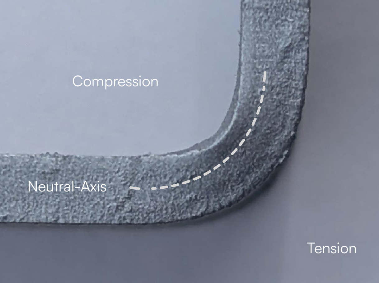
The Neutral Axis
When sheet metal bends, the outer surface stretches while the inner surface compresses. Somewhere between these extremes
lies the neutral axis, a theoretical layer within the material thickness that experiences neither tension nor
compression. The position of this neutral axis determines how much material is actually consumed by the bend.
K-Factor
The K-factor is a value between 0 and 1 that represents where the neutral axis sits within the material thickness during
bending. A K-factor of 0 places the neutral axis at the inside surface, 0.5 at the centerline, and 1 at the outside
surface. In practice, the K-factor typically falls between 0.3 and 0.5, depending on material properties and bend
radius. This seemingly small detail significantly impacts flat pattern accuracy.
Bend Allowance
The bend allowance represents the actual length of material along the neutral axis that forms the bend. It accounts for
the arc created during bending and ensures the flat pattern has the correct length. The bend allowance is calculated
using the formula:
BA = (π/180) × Angle × (Radius + K×Thickness)
where the angle is in degrees, radius is the inside bend radius, K is the K-factor, and thickness is the material
thickness.
Bend Deduction
The bend deduction is the amount of material length that must be subtracted from the sum of the two flanges to arrive at
the correct flat length. It represents the difference between the apparent length (if the flanges extended to their
intersection point) and the actual length along the neutral axis. The formula is:
BD = 2×(Radius + Thickness)×tan(Angle/2) - BA
Understanding bend deduction is essential for creating accurate flat patterns that fold into parts with the correct
dimensions.
Material Considerations
Different materials behave differently during sheet metal operations. Aluminum is lightweight and highly formable but
has lower strength than steel. Stainless steel offers excellent corrosion resistance but requires greater forming forces
and has more springback. Cold-rolled steel provides good formability and strength at economical cost. The choice of
material affects everything from minimum bend radius to hole edge distances.
Design Principles
Successful sheet metal design balances functionality, manufacturability, and cost. Flanges should be sized appropriately
for their purpose while minimizing material waste. Bends should use radii appropriate for the material and thickness.
Holes and cutouts should maintain adequate edge distances to prevent tearing during forming. Features should be arranged
to minimize the number of operations and tool changes required during manufacturing.